Summary
- In the last article
- Why did I need a second bike “brain”?
- The plan & How it became more complicated
- Reverse engineering or how I learned to speak motor
- How does it work?
- In the next article
Disclaimer
In this series of articles, I’ll describe my journey into building an electric bicycle. Those articles, including the reverse engineering part, are not meant as a guide to building your own. I offer those resources in detail for educational purposes, and I cannot be held responsible for any consequences resulting from using the material I provide.
In the last article
We discussed (yes, we, this is a conversation, there’s a comment section!) why I’m building this electric bike, how much it costs, and what’s important to buy. If you haven’t read it, you can do so by clicking here, but you don’t need it to understand this article.
Why did I need a second bike “brain”?
The bike is composed of 3 main components: Controller, Battery, and Motor. The controller controls (who knew!) the speed limit, lights, and the level of pedal assistance… it basically translates user inputs into information for the motor while keeping everything under the defined limits of the system. That is why I consider that the controller is the first “brain” of the bicycle.
To program some values in this controller, we use the display and buttons, and sometimes some secret menu hidden in the controller. In other terms, some values are tweakable by users, such as wheel size, speed limit, and number of pedal assist levels…
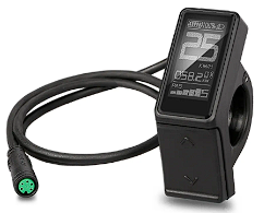
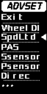
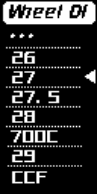
The DM03 display is the one I selected because I didn’t need more features.
The screenshots show the different parameters a user can change by accessing the advanced menu.
So why did I need a 2nd brain if I had access to those!?
Do you know about software-locked features? Those are features that are physically available for a user but are locked by software. For example, let’s say you buy a car. This car has seat heating capabilities. which means there are physical resistances in the seats, and by the push of a button, you can comfortably heat your frozen bottom! Unfortunately, the manufacturer of the car prevents you from doing so by software, and you need to pay to access this feature, even though the car is yours. In case you didn’t know, this exact example isn’t made up and an actual well-known car brand did that…
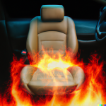

I asked DALL-E to generate images of free ways to heat car seats. But it looks more
like the mailbox of the car brand, after implementing their new lucrative “idea”.
I believe this is wrong. Locking implemented and functional features on a purchased device behind a paywall is an awful practice. Now if you’ve read the first part of this series of articles, you know this began because one of my friends has an electric scooter. The speed limit of this scooter is limited to 45 km/h and can be upgraded to 55km/h… By a paid software upgrade.
But I’m not buying a scooter or a car, I’m building my own bicycle and its systems are unlocked so why the hell am I writing all this, besides the fact that I’m not bothering enough people with those opinions of mine!? Because of regulations.
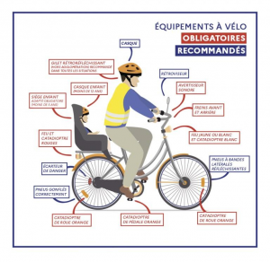
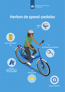
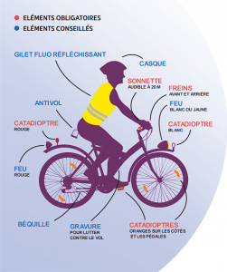
Safety rules from France, The Netherlands, and Belgium. To be honest,
a huge amount of bikes I see every day are not safe according to those visuals.
See, an electric bicycle in some European countries is limited to 25km/h. Most electric bikes have 250 Watts engines (maximum legally allowed), and can easily reach 30 to 32km/h. This means most consumer electric bikes sold today can go beyond the limit imposed by software. Now there is a reason for this limit, like all limits, and the reason is safety.
Now let’s say you have an electric bike that goes up to 32km/h, but you’re a reasonable person and as you should, you only reach this speed on private property where you can injure no one but yourself. The moment you use this bike on the road, independently of the speed you’re going, you’re riding an illegal bicycle and you can be fined and your bike confiscated. You don’t want your awesome bike taken away from you, and me neither!
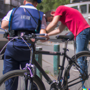
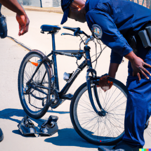
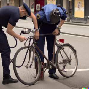
If those policemen look weird, it’s because they’re AI-generated by DALL-E.
They’re still taking your bike away though!
In order to prevent this situation, you would need your bike to be locked in a 25km/h mode, and be able to unlock that mode when you’re on private property. This is what the “2nd brain” is doing. It allows overriding the parameters set on the controller by the display. In other words, you can switch between speed modes in a way that you’re the only one aware of this system.
The plan
When I had this idea, I did some research and found someone had a similar setup however, they use a magnet and a hall sensor. It seems like a good idea, but what if you lose the magnet? What if someone understands what it’s for… Too many “ifs” for me.
My plan was to replicate what this person did, but adapt my own input system, because why would you re-invent the wheel? So I researched more, tried to understand which controller I had, and found all the possible information on my components. I wanted to know everything, and for that, I had to communicate with my controller.
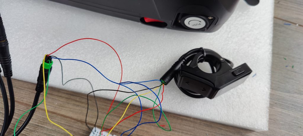
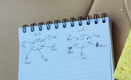
On the right, you can see a diagram of the connectors. Male and Female are mirrored.
If those connections between the display and controller look sketchy, it’s because they are.
I didn’t receive the additional cables I ordered, so I Macgyvered it!
Fortunately, there is some documentation online, and at this point, this is what I know:
My motor is a hub motor, my connector suggests a UART (A.K.A Serial) communication between the display and controller. This means that technically, it’s similar to the BSSHD motors (mid-drive motors), and I could use this nice software I found!
But I couldn’t. I triple-checked my connections and deduced that the problem was the communication protocol. This means that any previous resource I found for BSSHD is not compatible with my kit, including this beautiful groundwork that sped up my research.
Reverse engineering
(or how I learned to speak motor)
As I couldn’t find any documentation about my controller, I decided to investigate: If you set the speed limit through the display, it should send a command to the controller. If you know the communication protocol and can listen, then you can learn their language and become the man in the middle. And this is exactly what I did!
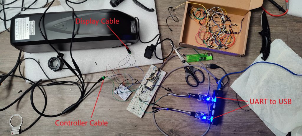
You can see (or not, it’s quite messy, to be honest) in this picture that I connected the display and the screen together through a breadboard. On this breadboard, I also plugged 2 UART to USB devices into the transmission pins from the display and controller. Thanks to the software Device Monitoring Studio, I could listen to both the controller and display and see this communication live on my screen!
“Someone plugged 2 UART devices into his e-bike, you won’t believe what happened next!”
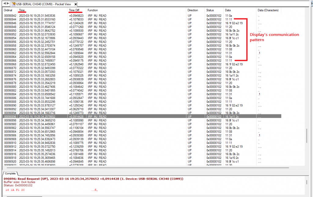
Window of the Serial communication log from the display transmission side. It’s important to note that synchronization is key as the Time and Time Diff column gives you precise information on which response code corresponds to which command. The response codes here are not visible as the controller side is in another tab.
I assumed the communication would only happen when a command is sent, for example, set the speed limit on the display, the controller receives the speed limit, saves it, and sends back a success/error code. However, the display continuously sends the same information over and over. So what really happens is that we set the setting on the display, and the display keeps sending it to the controller… Strange! But not surprising.
At this point, I knew how the communication was happening, but not what was being said. For that, I needed to do some experiments such as using the display to send a command to the controller and understand what was happening. Thanks to some response codes being the same as the ones available on this page, I quickly figured out the different codes and gathered all the data I needed.
I know you like to see messy, work-in-progress spreadsheets, don’t lie!
It was quite fun to understand this communication.
This was no Turing VS Enigma, but fun nonetheless!
How does it work?
- The display initiates the conversation with the controller, except for startup.
- The controller sends “00” at startup – The display responds with “00 20”
- Then the display continuously sends commands, and the controller responds.
- There are Set commands and Get commands
- Set commands have the prefix: “16” and are made of 4 bytes, 5 for speed/PAS.
- The last byte of the Set Speed command is a CheckSum8 Modulo 256.
- Get commands have the prefix: “11” and are made of 2 bytes.
- The display saves the settings and continuously sends them to the controller.
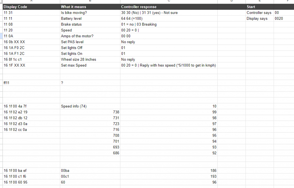
Here is a table of the commands with some explanations.
| Display Code | Command type | Function | Controller response |
|---|---|---|---|
| 11 31 | Get | Is bike the moving? | 30 30 (No) | 31 31 (yes) – Not sure |
| 11 11 | Get | Battery level | 64 64 (=100) |
| 11 08 | Get | Brake status | 01 = no | 03 Breaking |
| 11 20 | Get | Speed | 00 20 = 0 |
| 11 0A | Get | Amps of the controller? | 00 00 |
| 16 0b XX XX | Set | Set PAS level | No reply |
| 16 1A F0 2C | Set | Set lights Off | 01 |
| 16 1A F1 2C | Set | Set lights On | 01 |
| 16 8f 1c c1 | Set | Wheel size 28 inches | No reply |
| 16 1F XX XX XX | Set | Set max Speed | 00 20 = 0 | Reply with hex speed (*5/1000 to get in km/h) |
Speed setting
The easy way is to get the command from the display, then you’re sure it works.
Otherwise, you can calculate it:
The speed is coded on 2 bytes, the minimum is (00 4a (Hex) – 74 (Dec) – 10km/h), and the maximum (02 e2 (Hex) – 738(Dec) – 99km/h).
Now to build the command, calculate for a speed, say 25km/h: (738/99) * 25 = 186, in Decimal. Now we convert this number to Hexadecimal “00 BA”.
Perfect! Now we add the prefix and checksum and we have our command:
“16 1F” + “00 BA” + “EF” -> “16 1F 00 BA EF”.
And hopefully, the controller replies with… “13 88”.
Now you also talk motor! Moooooootoooooooooooooor!
In the next article!
In the next article, I will dive deeper into the electronics and program of the 2nd brain. The different problems I encountered and the new features I added to my bike. I will also post the source code, so a very technical and exciting post ahead 🙂
Thank you for reading the entire article, I hope you enjoyed reading it, and that it has inspired you, and if that’s the case, feel free to share it. Comments are open, feel free to drop any suggestion or comment there!
And as you’ve been patient enough, here is the first photo of the “2nd brain” of my bike!
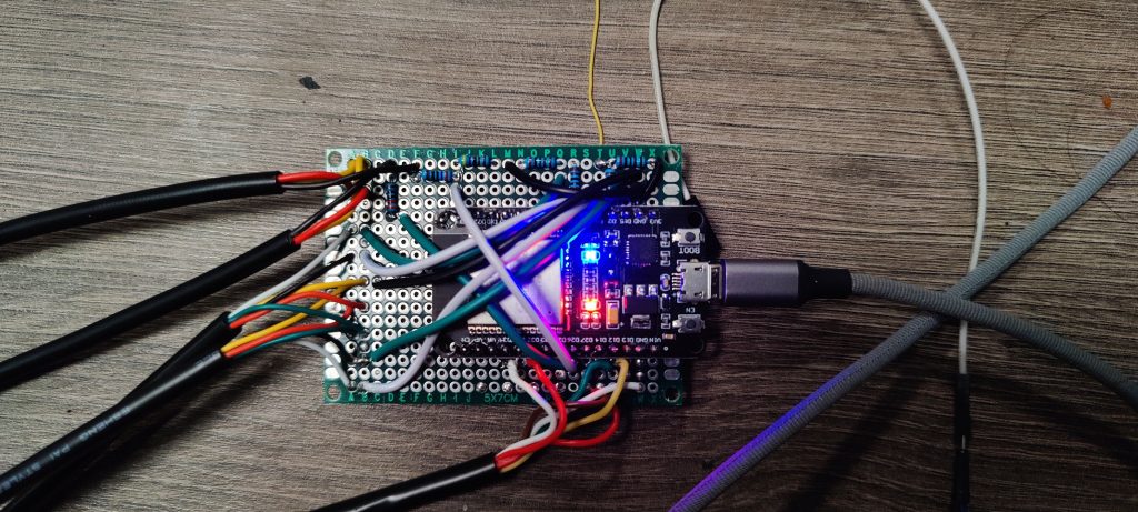
Tadaaaaaaaa! I hope you’re curious to know how it works, and the program behind it! You can have some guesses in the comments 😉